Technique - Fixing a Medion MD30919 PO TFT monitor
I don't recall exactly when I bought this monitor, but it's most likely 2005 or 2006 when Aldi supermarkets had this on sale. This 19 inch 4:3 ratio monitor was quite expensive with 300 euro back in the days. But hey, it saved a huge amount of space on my table and it was quite the difference compared to the 15 inch CRT I was using till then.
Unknowing of it's age, this monitor was at least 10 years old and I was satisfied with it. Although some programs would be better to view or work with on a wider screen, I didn't see any real reason to replace it with something new. I just awaited the day it would die as I'm just not someone who replaces equipment because there's 'something better' to get.
 Friday the 25th of September 2016 marked that day. If you have this screen yourself, you probably also know that the switch to really turn the screen on or off is at a hard to reach place (I don't like to have quipment on stand-by)
The cabinet were the monitor was placed made the switch almost impossible to reach and thus the screen was on stand-by most of the time, against my own principles. This also meant the screen was always on and the power supply was always 'warm'.
Getting the computer to do a back-up and really turning the screen off made the power supply go dead. With a soft ticking noise I saw the blue LED, that shows if the screen is on or in stand-by mode, flash briefly, without the screen powering up any further.
With the suspicion of bad capacitors, I first had to arrange an emergency-monitor. I was quite lucky to find the old 15 inch monitor of my dad in the attic and then look for the problem something like a week later. Besides bad caps there were also quite a lod of bad solder joints.
Opening the monitor
When fixing other LCD/TFT monitors, I found that many things are clicked into place. Most of the time, you can't always get the thing open without damage, a reason why fixing it can be hard sometimes. Opening it takes longer than desoldering the defective parts and placing the new ones.
How different would that be with this monitor! This one was even easy to open.
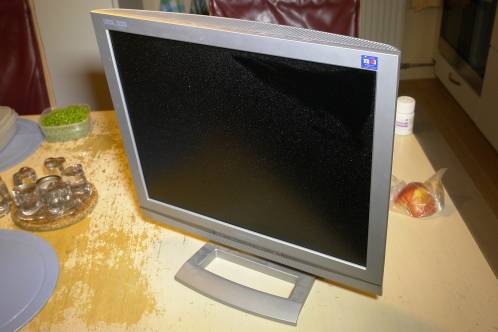
 First, take the monitor of it's base and place the monitor on a table with the screen facing a clean and flat table-top. My hobbyspot does not provide the space for this kind of stuff, so I used the kitchen table.
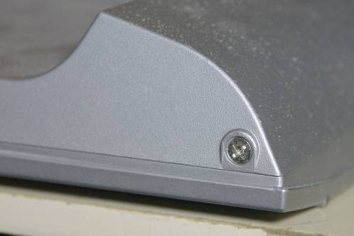
On the bottom of the monitor-housing are 4 short philips-screws. By removing these, the front-bezel around the screen comes loose. You can see one of these screws on the picture.
 The bezel is now loose. Rotate the device in such a way the top of the housing is facing you (the panel still facing the table-top) to release the top-part of the bezel.
 Lift the edge slightly and push it up gently. I could not find real notches, but you can manipulate the top part of the housing, by pushing a little near the ventilation-slots, to free the front-bezel.
I had to carefully prise the edge to get it loose, but not much.
Grab firmly both the front- and backpart of the monitor and turn the whole device over, so you're facing the panel. You can now lift the bezel that's at the front and you can see the panel itself.
 After removing the bezel (and put it away in a safe spot) you can start loosening the screws that hold the panel.
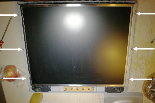
The panel is held in place with six screws. The white arrows in the picture show where these screws are located.
These are the longest screws you will find in this device, so you can hardly mix them up with screws we will find later.
 After removing all the screws that hold the screen, you need to disconnect a few cables to get to the power supply. This can be tricky to do on your own and an extra pair of hands is useful.
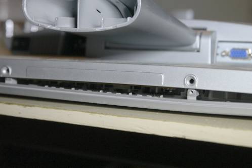
At '1', the connections for the backlight-tubers can be found, in 2 pairs of 2 connections.
'2' marks the control-cable that drives the panel, which is a hard to remove, wide connector.
Everything is extremely well shielded by use of aluminium-tape, so you will have to remove some of it in order to get to the connectors and pull them from the power supply.
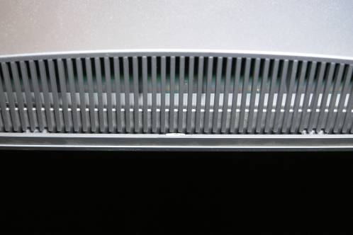
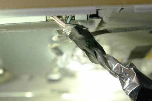 The backlight-connectors in detail. These are the 2 easy ones. Probably in an attempt to cut corners, or because the screen was almost impossible to assemble, 2 PCB-connectors have been omitted from the PCB.
Instead, they soldered wires to the PCB and connected to female receptacles to the wires, which in turn receive the male backlight-connectores. To shield everything, everything is wrapped in aluminium-tape like there's no tomorrow.
You could use something to place between the housing and the panel itself to hold the panel up, but an extra pair of hands is easier.
 If you disconnected the backlight, you can easily turn the panel around and carefully place it down to work on the connector that goes to the controller (marked with '2').
I only removed this connector after I removed the metal cover of the power supply. You can't reach it otherwise and pulling the connector by pulling the wires did not seem such a good idea.
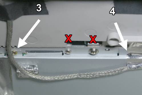 To remove the cover from the power supply, you need to remove 8 screws. The cover has a few 'wings' that are held in place by M3-screws and those are the only ones (marked with '3') you need to remove in order to remove the cover. There is 1 big screw that connects the monitor-base to the rest of the monitor, but that's not in this picture.
Pay attention for '4'. There are some screws hidden underneath the tape. Removing the tape is the only way to find them.
Don't remove the screws marked with the red 'X'! There is nothing bad happening if you do, but you don't need to remove them to get to the powersupply.
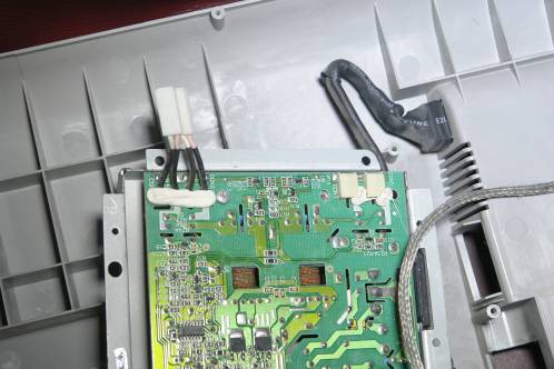 Pay attention when removing the cover. On the picture, you can see the 2 wired backlight-connectors. The cover has been made by taking SMT-connectors into account, so you will have to pull these wired connectors through the whole of the metal cover to remove it.
You can see that I also removed the bottom cover, but that's not necessary.
Caution!
If you powered the monitor shortly before removing the cover, there is a chance there is still a high voltage present in the power supply. There's a big capacitor with a working voltage of 400 Volt in it.
Check this with a multimeter and discharge it if necessary before you start to remove the power supply itself.
5 (or 6, sorry, I don't recall exactly) screws hold the power supply in it's metal cover.
Lift the power supply PCB by pulling it straight up a few centimeters: a connector that powers the control-circuitry is disconnected this way.
After that, you can unscrew the earthing-wire that is located UNDERNEATH the PCB.
The black, heat-shrinked cable to the mains-switch is only held by a tie-wrap. After cutting the tie-wrap, you should be able to press the white connector and pull the wires from the PCB.
The powersupply out of the monitor
 And that's the power supply in front of us.
I'm impressed to be honest. Decolourization is very good after a good 10 years of use. I know quite a lot of PCB's that show far worse signs of wear because of heat, mainly found around the transformers that power the backlight.
Besides that, there seems to be a lot of noise-supression. Literally every part seems to have some sort of measure to control emission to the outside world. This could be a sign that corners have been cut and the design itself is bad, but I get the feeling that everything has been done to at least minimize interference.
The capacitors, main suspects in this case, don't look suspicious at all. I expected to find at least a few bulging, but I couldn't find any.
Evenso: just replace them all. Not only the big ones, but the small ones as well you can find in this supply.
Partlist:
| Type | Amount |
|---|---|
| 10 uF 50 Volt | 2 |
| 47 uF 50 Volt | 1 |
| 100 uF 25 Volt | 2 |
| 220 uF 25 Volt | 1 |
| 470 uF 25 Volt | 6 |
The verdict
 Suspecting bad caps is 1 thing, replacing them is 2, but researching if that is really the cause of the malfunction is 3.
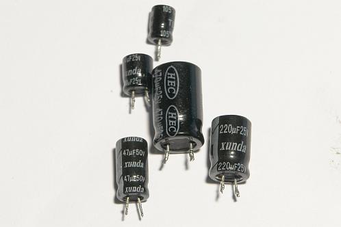
The first suspicion is the brand 'Xunda' for the smaller caps and 'HEC' on the bigger caps. The first did not ring a bell at all, but I have had bad caps from HEC before.
I decided to check the capacitors with a Peak atlas ESR60 and LCR45.
Surprisingly, the biggest capacitors (470 uF) almost all were in decent condition. The LCR45 showed that 4 of 6 caps had a capacity that varied from 407 to 430 uF and the ESR was between 0,26 and 1 ohm. Even at 1 kHz, specifications were still very good with capacities that were around 330 uF.
Only two of these were out of spec with capacties down to 360 and 390 uF and an ESR of 7 and 1,4 Ohm respectively. Ofcourse, testing them at 1 kHz gave ridiculous results.
 Things got funny with the smaller caps.
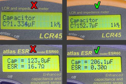
The 220 uF cap was immediately labeled 'bad'. According to the LCR45, the capactiy was only 1,3 uF at 1 kHz.
The ESR60 rated the capacity at about half the specified rating, but the ESR went astronomical with almost 17 Ohm. Both values can be seen left in the picture.
I compared these bad ones with new Jamicon caps with equivalent rating. The capacity goes down to 152.7 uF at 1 kHz according to the LCR meter. Connecting it to the ESR-meter gives a capacity of 206 uF and an ESR that is only 0,3 Ohm. A clear difference with the old cap.
That the caps were really the issue in this device was clear when I checked the 100 uF and 10 uF caps. These were so bad that both the ESR60 and LCR45 couldn't give a reading and showed 'Open circuit'.
When replacing the caps, I found that I didn't have a 47 uF cap with a 50 Volt rating in stock and the electronics-store didn't have them as well at the time. I apparently forgot about that when I got home, so when I replaced all the caps except for 1, the monitor went completely dead: no flashing light with ticking sounds from the supply anymore.
A week after, I spotted the cap I 'missed'.
This 47 uF 50 Volt cap was exactly the one that powers the off-line controller, so that was nothing of a coincidence.
'Off-line' sounds confusing when you compare it to 'being off-line' (not connected) to the internet. In this case, the controller is called 'off-line' because it get's it's power directly from the mains: 'off the line' so to speak. Most controllers for switchmode power supplies are fed via primary or secondary windings on the transformer.
 After some cleaning, I found a Panasonic FC capacitor with the right specifications. I replaced the cap on the PCB and checked the old one.
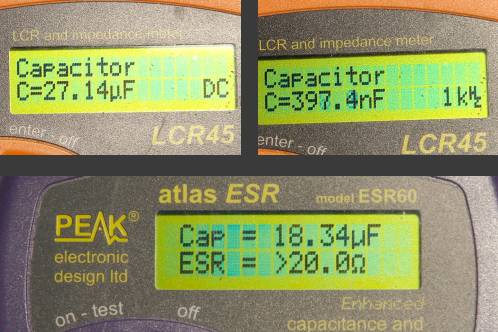
The capacity at DC wasn't that bad with 27 uF. At a testfrequency of 1 kHz things got funny and there wasn't even 400 nF left. Healthy caps at least show a quarter to about a half of the capacity on the housing.
The ESR60 labeled this one as 18 uF, but the ESR was so high it only showed 'greater than 20 Ohm'.
 To compare, I tested an old Philips cap, because I only had 1 Panasonic capacitor and I already soldered it in before I got the idea to test it first.
As the Philips capacitor is at least 30 years old, the specifications were quite good with a capacity of 32 uF at DC and 18 uF at 1 kHz, according to the LCR45.
Although the ESR60 rated this one with a capacity of almost 30 uF, the ESR wasn't really high with 1,9 Ohm.
Bad solder joints
Even before replacing the caps, the state of a number of solder joints got my attention.
I got the question how a bad solder joint looks like quite a lot through the years. Well, this is a good example.
Thirst, there are a few things to keep an eye out for when you suspect bad joints:
- A bad solder joint mostly looks like a joint with an extra, not-shiny edge around it. Sometimes you can see this very clearly, sometimes you can't.
- Components that feature frequent mechanical stress are far more susceptible to bad joints. Pushbuttons, connectors and heavy parts like big caps, resistors, transistors and chokes, are the prime suspects
- Components that tend to get hot, are also a root-cause of bad joints. The frequent warming and cooling down exerts mechanical stress that can eventually destroy a good joint.
If you look for bad joints, look for the components that are bound to heat up, like transistors or diodes on a heatsink, small transformers or chokes and resistors - The most annoying thing about this: bad joints are also found in places where you least expect them and where you can have a hard time recognizing them. Just apply some fresh solder as much as possible to prevent problems.
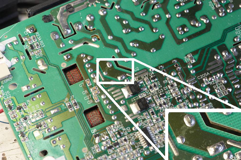
Many things mentioned above could be found on this powersupply. Especially the joints from the heatsink were almost all bad, just like the bigger joints from the mains-connector and connector to the mains-switch.
The picture shows an enlarged picture from the 2 worst joints I could find.
Taking care of bad solder joints
Just applying some fresh solder to especially bigger components is not recommended. Most of the time, lead-free solder is used and mixing leaded solder with it can cause problems to resurface soon after fixing them. Most of the time, a solder joint made this way will have a dull appearance.
If you want to do it right, you remove all the old solder with solder-wick or a desoldering-pump and then apply new fresh solder. You can apply lead-free solder, but I prefer the old, leaded stuff.
Turning the screen back on again
 Before you close the monitor again, wait a while. Maybe more is malfunctioning than you would expect and it would be a pity if you find out after you assembled everything again. Ofcourse, you will have to make sure you put everything away in a safe manner and connected just like it would be in normal life.
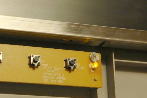
I connected all backlight-tubes and control-wires and put the panel down on a stable surface. I plugged it into mains power and... Hey, there's a yellow light. That's a good sign!
 A short press on the on/off switch at the front and: YES! It's back to life!
About 12 Euro in parts saved this screen from the scrap-pile.
Ofcourse, I disconnected the screen from the mains and put everything back the way it was. It was reconnected to my computer after that, although I bought a new screen in the meantime, as a 15 inch 1024 x 768 pixel screen is fairly small...
Something else broke down...
To take the pictures you see here, my camera was on the table as well.
After the first attempt to fix it was paused because I had overlooked that one cap, I started cleaning up. My photocamera went up as last. Well, it was meant to go up anyway... A stumble on the stairs made it bounce down almost the complete stairway. This wrecked the screen. Ofcourse, I took care of that!