Technique - Swing-arm desk lamp with fluorescent tube converted to LED
Caution! Dangerous voltage!
This conversion handles components that work on mains power and a power supply that does provide a galvanic isolation, but outputs 48 Volt DC, which I consider to be a dangerous voltage. The LED-driver used in this conversion delivers a maximum of 45 Volt on its output and in my case, one can touch that voltage.
A swing-arm desk lamp...
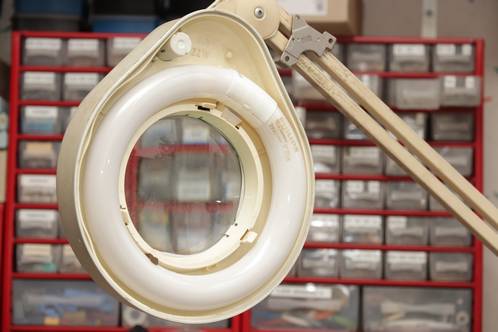 Probably everyone knows this type of lamps. An arm with 3 'elbows' and some springs here and there, that can be attached to a desktop with a special clamp, which makes it possible to position the light in almost any way possible. A circular fluorescent tube provides the necessary light and the built-in magnifying glass makes sure you can look at small items easily.
Technical malfunctions, the flickering and two LEDtube I found in the trash, got me thinking about converting these lights. I warn you though, this is not a simple retrofit!
Queensday-buys
Both my hobbytable as the table I write this article at, are lighted with said lights. The fluorescent was once protected with a cover, but because it most likely broke or went missing, these lamps were sold. I could buy them for a fraction on the Queensday-markets. The missing cover never really bothered me.
One of them did start to malfunction at some point. Ever more often switching it on did not do a thing. The visible starter also did not glow. If I would hit the fixture quite violently, the starter would glow and the tube struck eventually, to stay on reliably after that.
Convert it?
Especially the flickering before the tube strikes (which especially in cold circumstances could take 10 seconds) started to annoy me. I had already scavenged the small PCB from a compact energysaving fluorescent bulb with nearly identical power, to see if I could use it to remove the magnetic ballast.
But getting the PCB inside the fixture was hard because of limited space and putting it at the spot where the ballast sits meant getting long wires to the tube. In a compact energysaver, these wires are just a few centimetres long and extending them enlarges the risk of the tube not striking. I also had to get a cable with 4 wires, rated for mains current in it up to the fixture, something I was not keen on doing.
Something with LEDs seemed to be the better choice. That would finally be a usefull conversion in stead of some DIY-experiments with LEDs I took up so far, but never got beyond that point.
LED tubes in the bin...
I saved two V-TAC LED tubes from the bin a while ago, by the looks of it just discarded because the outer tube, made of glass, was broken.
That there even was an outer glass tube surprised me, because the inside consisted of a fairly sturdy plastic tube containing the LEDs and electronics, which looked strong enough to sustain it's own weight.
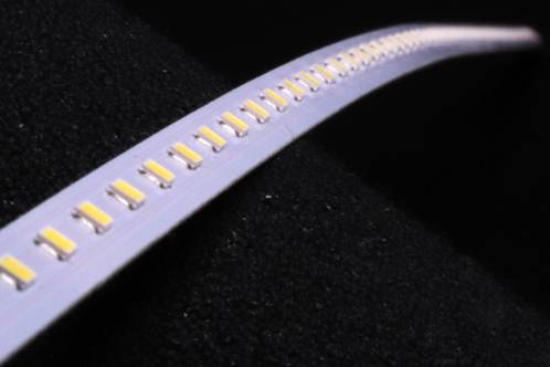 They had been out in the rain for a while already, but were still functioning and the inside held a kind of solid LEDtape which measured about 100 centimetres in length, plus another piece of about 20 centimetres long.
That's no coincidence with the standard sizes of fluorescent tubes (100 and 120 centimetres). It makes for a cheap way to make a LED substitute for both sizes.
Both tubes held a quite staggering amount of 120 LEDs.
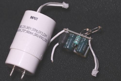
5 Groups of 24 LEDs in series were in parallel and were fed by a small power supply in one of the sockets.
That powersupply is the reason to slightly distrust these tubes when it comes to their lifetime-expectancy.
The PCB with all the components really did fit exactly in the socket, did not have any air-ventilation and the electrolytics did not only get to endure the heat from the transformer they were positioned right against to, but also the accumulated heat from all the LEDs. The tube would only get convective cooling from the outside, which means hardly any cooling at all.
What kind of LEDs?
 As I couldn't use the tubes itself, I got the multimeter out to test what kind of LEDs where in them. That wasn't all that easy. Set to the diode-test the LEDs remained dark.
A carefull voltage reading while switched on revealed every group of LEDs sees about 175 Volt, with one side directly referenced to mains as well. If I wanted to convert this, I would reallt have to think about shielding the LEDs.
Though the PCB showed a marking that took me right to Bridgelux itself, I wasn't completely certain which type of LED was on 'my' tubes, as the same package-size features multiple different models.
I also wanted to be able to dim the LEDs and that was impossible with the original power supply. Some messing about with resistors that - considering their value and location on the PCB - had something to do with current-sensing, did bring the light-output down, but when I wanted to go even lower, the power supply would stop working.
This conversion surely would not be a matter of 'just' replacing the tube with a LED-replacement. The weight poses an extra challenge. If the fixture gets too heavy, the arm will drop down by itself.
This meant I had to weigh all the parts and compare them with the current weight.
Starting the conversion: finding the right components
Dimmable LED-drivers on mains-voltage all proved to be too long or too wide to fit in the space where the magnetic ballast currently resides. If I did find one that would fit, the electrical specifications were not right. I thus had to find a separate power supply and LED-driver.
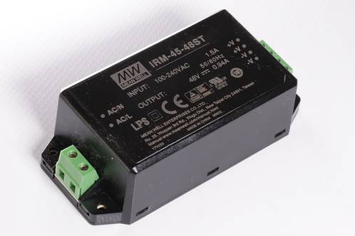 A IRM60-48ST by Mean Well, a power supply with an output voltage of 48 Volt and 60 Watts of power would just fit in the ballast-enclosure if I removed the plastic enclosure around it. I wanted to be able to really switch off the power supply, so the switch would have to move from the fixture to the base (lower arm) of the lamp.
The Mean Well power supply proved to be built far more compact than I expected. Inside the plastic housing was a fully potted PCB really filled to the brim with components. Making it slightly smaller to fit into that magnetic ballast enclosure was not possible. I had to make a new outer enclosure as I would have to mount the supply on its side.
The picture shows a somewhat less powerfull variant on the 60-48ST, namely the 45VA type of the same series, providing the same output voltage. I used this in the second lamp as the current drawn proved to be not even half of what the 45VA-type can deliver.
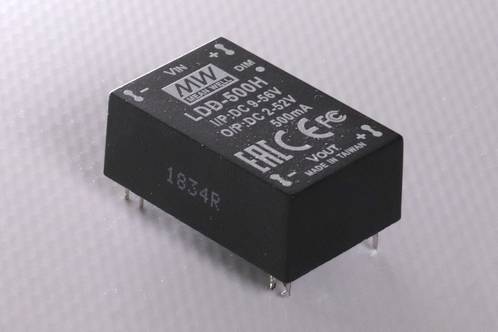 As the LEDs work better on current than just some voltage, I also ordered a LED-driver from the LDD-serie from Mean Well, which you can get both wired and with PCB-pins.
The components explained
The choice for the IRM60-48ST supply could seem to be a bit odd, when you figure out that the LED-driver only supplies 500 mA max. There is some loss added to that though, the driver isn't ideal.
At an efficiency of about 90 percent I will need some extra power. Besides, I want to be able to dim the output. These drivers dimm with PWM so the LEDs are switched on and off in rapid succession.
I have no idea what that will do to the voltage on the input. If that will be loaded in a pulsed manner (something I don't hope as the datasheet does not mention it) the power supply gets to take the abuse.
Besides, some headroom can't hurt. Especially as the power supplies in my situation will hardly have any air-cooling at all.
A test with the LEDs parallel
 But, you should not put LEDs parallel to eachother!
Yes, this is a rather hard-to-ban mythe, which is partially true. Putting LEDs parallel in a circuit without giving each group it's own proper current-limiting measure isn't always recommended. In this case it's posible, as the LEDs were in a partial parallel configuration in their original situation already.
First, I cut the 120 centimetre long LEDstrip into pieces. Each group of 24 LEDs, which drew about 23 mA, was further divided into 4 groups of 6 LEDs. Four groups would roughly pass 100 mA and 20 groups of 6 LEDs would draw a total current of 500 mA.
Apparently, my plans differed at first, as I ordered a driver capable of delivering 600 mA in constant current mode. To test my setup, I soldered all the 20 pieces of LEDstrip beside eachother, connected them to the driver and the driver with the power supply, and switched on. No problems whatsoever and a nice amount of light was the result.
The LEDs did heat up quite much though, something I expected to happen because they were so closely packed together.
 Using a jigsaw, I cut out a mounting plate in the shape of the fixture's inside out of 1 millimetre thick aluminium plate.
Keep the speed down when sawing through aluminium. Aluminium-burrs tend to clog your tool pretty fast, which will slow progress significantly.
If you want, you can protect the piece you're working on with masking tape as used for painting. Sticking it to the bottom of the base of your jigsaw is another option. It will prevent scratching.
With a file, I got the shape slightly better and with a deburring tool, the sharp edges were removed. After an extra round with the file the metal plate now fit inside the fixture's plastic interior.
A tight fit: the LEDs on the mountingplate
 This metal plate would be the base to mount the LEDs on, though I wasn't really sure how exactly.
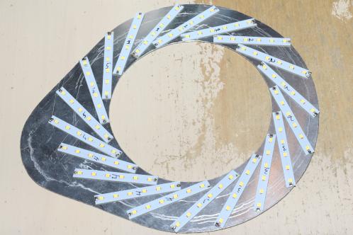
My first idea was a spiral-like setup (also because it just looks impressive) but maybe I could arrange them differently. That's why I first started test-fitting all the LEDstrips before I'd stick them to the plate for real.
The spiral-like setup proved to be the only logical one. That way, I could go by every piece PCB with a wire to put them in parallel. In any other configuration, wiring would be a tough job.
After a carefull degreasing I stuck the LEDstrips to the mounting-plate with common double-sided adhesive from the hobbyshop. Heat-conducting tape would have been better ofcourse, but I could not get it.
After wiring, which took quite some time, I connected the driver and power supply. With my eyes pinched I turned the power on and took a short endurance test, so see what the temperatures would do.
 After 10 minutes, the mounting plate had gotten so warm I could barely hold it. The infrared-thermogun showed it had risen to 54 degrees Celsius, and even slowly climbing.
How strange... The temperature of a LED itself wasn't a joke either. I got a bit scared when the thermo-gun showed 85 degrees. I turned off the power and started calculations again. Then, I found my error.
I think I originally took my calculations with groups of 4 or 5 LEDs, as I could (with some trouble) mount those pointing from the inwards out. That was a different total current, meaning it was now pushing too much current through the remaining LEDs.
With the right driver, the LDD-500H, another test was performed. Now, the plate stayed relatively cool at 42 degrees. The LEDs still heat up quite a bit to 65 degrees Celsius, but compared to being in the tube, they now feature quite some air-cooling.
An enclosure for the power supply
 The electromagnetic ballast, now obsolete because of this converison, was covered by a kind of metal lid, that exactly fits over the tray mounted to the arm of the lamp.
With the original enclosure unable to fit over the power supply mounted on its side, I had to think of something new.
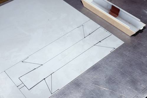
A piece of left-over PVC-plating at work got lines drawn on it, taken from the original lid, to stick to the original sizes as much as possible. The first one has a slightly different shape than the second one. It is the second one you see in the picture, that still shows the extra diagonal marking-line.
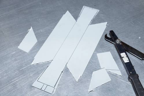 The guillotine shear took care of removing the extra material.
A sheetnibbler from one of my colleagues took care of the remaining bits to get to the desired shape.
I've left the ends untouched so far. Building the first one, I found out that the small notches that need to fit the tray on the arm, have to be made rather precise. If I was to cut the PVC to size already, I was running quite the risk the enclosure would not fit or stay put.
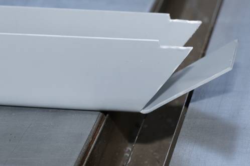 The hot wire bender at work was used to deform the PVC at almost any point. Some angled aluminium profiles were used to get the corners as sharp as possible.
The first one did not go down as smooth as the second one, especially because of knowledge gathered about the shape.
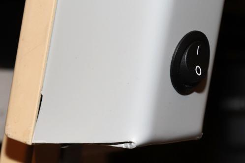 A step-drill was used to make a hole for the switch. I could not find a way to mount the LED-driver unfortunately, but it stays in place quite well inside the enclosure.
It was a bit of a pity to find out the plastic from the cable's strain relief had worn completely.
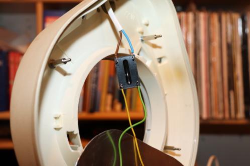 After soldering the cable rising up to the fixture from the arm to the LED-driver, I basically fumbled everything inside the fixture. I will be doing something about that later.
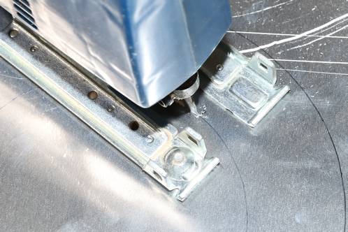
Stand-offs make sure the mounting plate mounts flush to the inside of the fixture and is about 1,5 centimetre deep in there.
I didn't plan it like that, but really is a necessity as I would be looking into the LEDs constantly otherwise, even if from the corners of my eye.
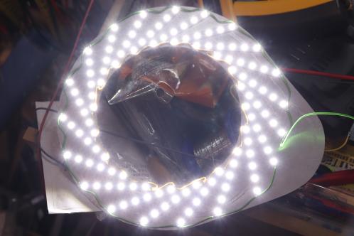
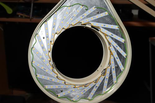 After putting the plate inside, this is the result. Ready for use.
To measure is to know!
This is all nice and such, but did I benefit from it? You bet I did!
The main thing I was curious about was the gain in light-output. I took measures of the best fluorescent tube and the LED-replacement. That also provided an unexpected result with the fluorescent I really didn't know about.
The sensor of a Voltcraft MS-1300 luxmeter was put on the table, with the lamp at 60 centimeter distance. This because I hardly ever have the light in its fully-up position. 60 centimeter therefor is a realistic distance between desk and lightsource. At both measurements, the temperature of the sensor was 20,2 degrees, measured with a Fluke 62 Mini IR thermometer.
I only started noting down values with the fluorescent as soon as it had struck succesfully. For two minutes, I recorded the light-output every 10 seconds. After that time-window, the increase wasn't that noteworthy anymore and I increased the interval.
The low values direct after striking of the tube and in the first 3 minutes to get to full output are no surprise: fluorescent tubes are known for this behaviour and not in a positive manner.
That's why I was ever more surprised that the light-output started to drop slowly 4 minutes after striking, to stabilise 24 minutes after striking and stay at 414 lux. I ended recording the output after 30 minutes.
The LED-lamp behaved far better. Not only does it feature a very bright 1935 lux light-output direct after turning on the power, it also only drops about 100 lux 16 minutes after switch-on, a decrease of about 5 percent. This compared to the quite bad 6 percent drop of the fluorescent that also outputs 4,5 times less light.
It's interesting in later measurements, to see if this decrease is down to the LEDs or driver heating up (or both).
Color-reproduction
From the early age of LED-lighting, when LED-lamps slowly started to win it over incandescent bulbs, the myth resounds that LED-lighting is't good at reproducing colour. These days that is a completely different story. The last 5 years (2019) LED-technology has been evolving rapidly and especially the colour reproduction has improved a lot.
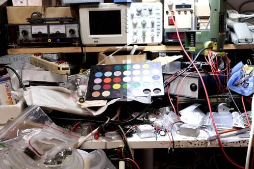
I unfortunately do not have a good method to test the colour-reproduction. The color-chart is from a supplier in plastics and likely only an indication. I tried to aim both lights as good as I could, but differences in their radiating pattern from especially the LED-lamp make for reflections on the color-chart.
The JPG-compression in the image also doesn't do the result any good, besides the vast amount of differences in screen-settings on the reader-side that also influence the resulting image.
With the Canon EOS800D on full manual, taking pictures in RAW, exposing everything as closely as possible and some editing afterwards, I do get to a result with some interesting differences.
For this test to be as complete as possible I also took a test with the old Sylvania FC22W colour 133 tube (A) (with quite some hours and bad colour-reproduction), the Philips Master TL-E 22W colour 840 tube (B) and the LED-substitute (C). The colourfull result is shown below.
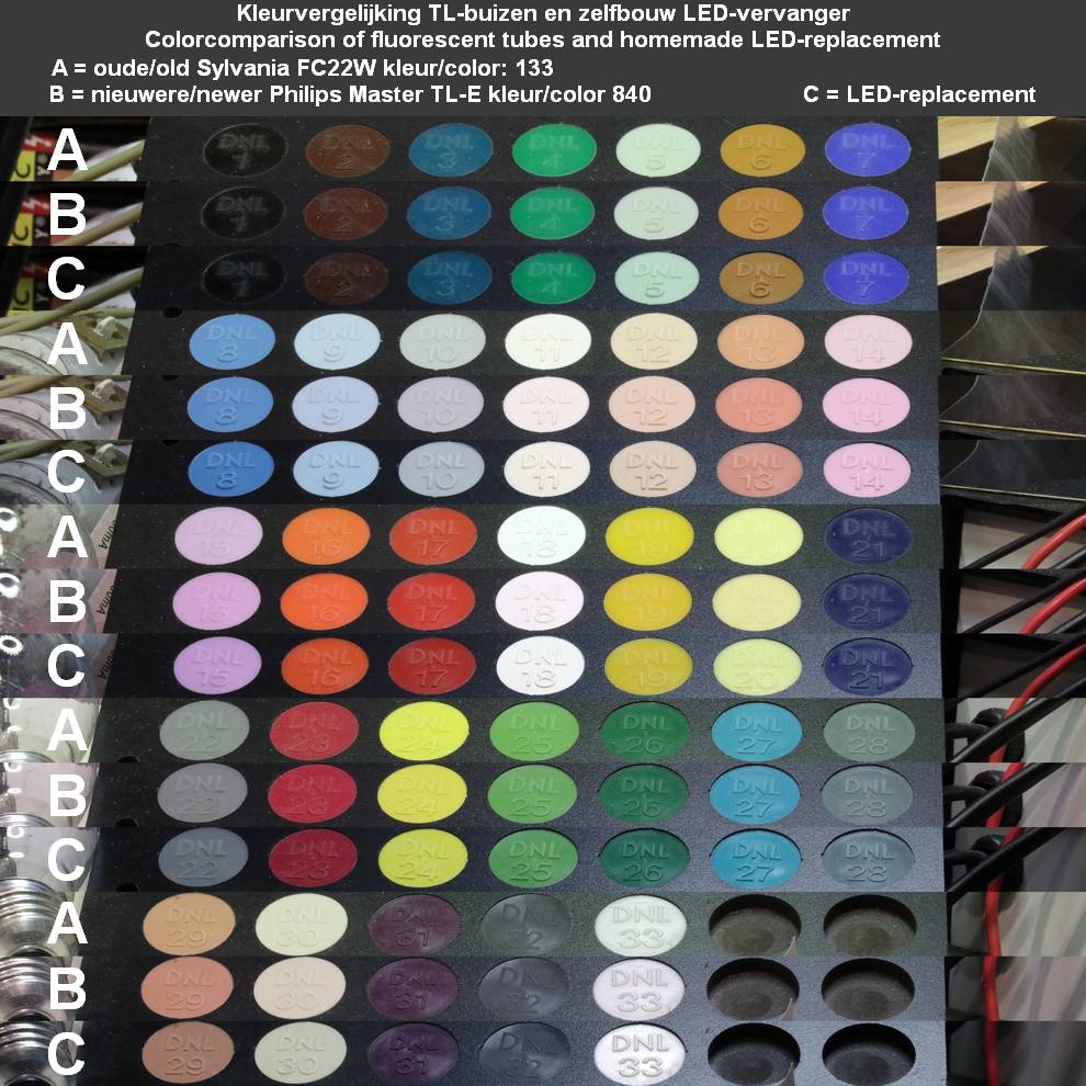 Even though there are so many steps taken that all have their influence on the result, the image clearly shows that the old Sylvania-tube isn't doing a good job. Especially the second brown color on the first row deviates from the rest.
Also the second till the fifth colour on row A2 are a bit hard to distinguish.
The fifth colour on row A3 clearly stands out: the green haze this tube puts out can be clearly seen in the colour. At the same time, it is visible that the 840 tube by Philips is doing slightly better than my LED-lamp, while both the first and second colour on row C5 clearly deviate from both fluorescents. It's just what you pay attention to.
In short: I'm really pleased with the result, especially when you think about the fact I was dealing with unknown LEDs. A really positive surprise is the colour-reproduction on an overall scale. White LEDs, still blue LEDs with a phosphor to create white light out of it, still tend to peak in the blue part of the spectrum. I really can't see that back on the color-chart I used. Though the LEDs are not as good as the 840 tube (though by only a fraction), they certainly beat the old Sylvania tube.
Colour-temperature
 I'm also fond of the colour-temperature. Because I could not pick the LEDs myself, I had to just face the colour-temperature of about 4500 degrees Kelvin of the LED-tubes.
I was in doubt about that. I find 3200K to be too warm for desk-use and 5600K too cold, although you get used to it quickly. The 4500K seems to be a nice compromise between these 2 'standard' values. It resembles light put out by halogen-bulbs and therefor is a nice light to work under.
Technical data
Besides the hard to measure and somewhat personal colour-temperature, there are technical aspects I can measure.
In light-output, the LED-lamp wins hands down when it comes to efficiency. I took measurements of that as well.
Mains-voltage measured with Multimetrix DMM220.
Current-measurements were done with a UNI-T210E current-clamp.
Currents drawn were measured at a mains voltage of 232 Volts.
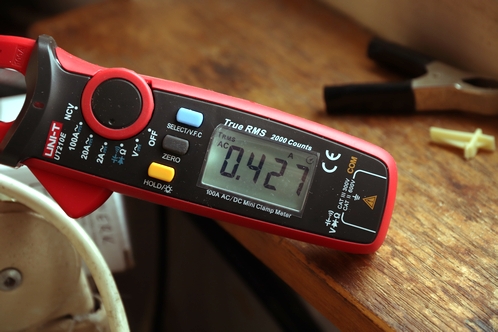 The fluorescent tube drew a quite staggering 0,43 Amps! That is an almost 100 Watts of apparent power!
Corrected with the cosinus phi marked on the magnetic ballast, active power is nearly 34 Watts. Expecting that the tube really does consume its rated 22 Watts of power, 12 Watts, slightly more than half the rated tube-power, is converted into heat in the magnetic ballast. Not such a crazy number considering how hot this part always got after prolonged use.
The measured current is quite remarkable by the way, as the ballast is compensated with a capacitor. But I got the impression this is one of those capacitors that is notorious for just going up in smoke at some point in their life, so it could be that it's not even functional anymore.
The Mean Well IRM-xx-48ST unfortunately does not come with figures considering the cosinus-phi. It could be these are compensated, but knowing Mean Well they would explicitly state this on the enclosure somewhere, or mention it in the datasheet and none is the case here.
In that case, current will only flow on the peaks of the sinus. I expect the current-clamp used to deviate when that happens and only shows the right values on clean sinus-waves.
Assuming that cosinus phi = 1, the measured current of 0,145 Amps equals a power of 33,64 Watts. That's very close to the identical performance of the tube, but at this power, it provides me with almost 4,5 times as much light.
The IRM-xx-48ST is 90,5% efficient. Slightly over 3 Watts is lost in the power supply.
The LDD-500H driver is about 96% efficient. From the remaining 30,4 Watt, 29 Watt remains.
 The current through the LEDs is a calculated 500 mA. As the output-voltage of the LED-driver is 3 Volt lower than its input voltage, the total available power for the LEDs is about 22,5 Watt. That means power is lost somewhere, the power supply's output voltage is greater than I expect it to be, or the current clamp deviates.
Evenso, the current measured isn't all that weird and it does really look like the power supplies feature power-factor correction.
It explains the only slight warming up of the supply and LED-driver, really nothing compared to the ballast that was heated up well and is a large lump of metal.
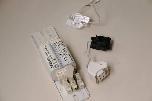
And thus, the magnetic ballast, switch, the starter-socket and the connection-socket for the tube remains. They have become obsolete, just like the tube itself.