Technique - Reworking a Cree XR-E LED
Word upfront
I don't doubt the manufacturer, but despite careful determination I'm not 100% sure I'm dealing with an XR-3 LED here. The soldering process however, hardly differs between all the different types out there.
Defective LEDs
 At work, some of these Lumoluce Lugano LEDspots (L05410WW 28L125) had to be replaced because there was hardly any to no output left. Not that strange after 7 years or so on a motion-sensor, although I was a bit surprised to find the LEDs to be at fault instead of the driver.
Because I was curious about what was causing the problem and I only had a laboratory power supply available at work (with the same result as the driver: no light) I took a few home to investigate.
A pretty obvious problem...
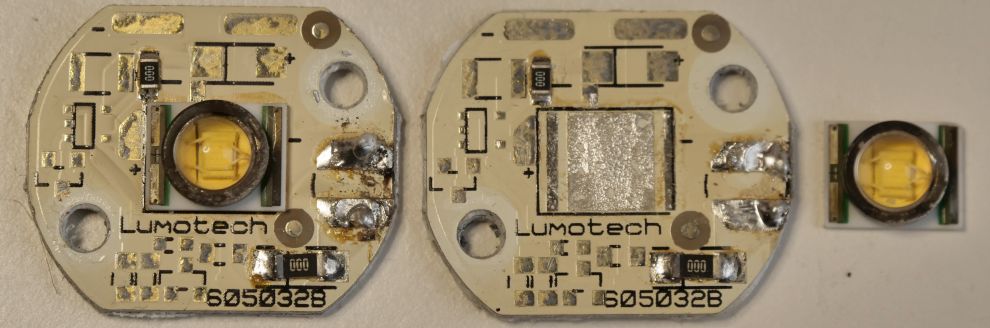
It was a short investigation into the cause, because when unscrewing the front of these Lumoluce fixtures that houses these LEDs, the LED-chip and its mounted lens almost fell off the PCB spontaneously.
Now that's a weird defect! Would this be down to heat, has this been a bad batch where the LED wasn't fixed properly to start with or was the wrong solder used?
An attempt at reworking it
As the LED itself still worked the way it should and it was broken already, I tried to see if I could rework this part. Normally, I refrain from soldering bare LED-chips as I just don't have the right equipment for it.
In this case, I could not go wrong and it would be a nice learning experience.
First, I checked if a flux-only treatment would be able to solve this. Downside is my flux is rather old so applying a normal amount was hard.
Besides I probably did not have my hot-air station set to the right temperature. The first attempt failed. With a rather distinctive 'click' a crack suddenly appeared in the gel-body beneath the glass lens and the whole lens detached from the LED-chip.
Well... I may have to think about exchanging this whole PCB with a new XR-E LED already on a PCB.
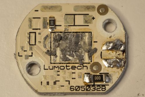 As I had another one left with an equally non-sticking LED, I went for a second attempt. This time I mixed pretty old solder paste with some flux at the spot where the LED should be, with a rather messy result.
This would not be a winner as well: though both the flux and tin got to the right temperature, there was either too little (or too many) to actually fix the LED into position. After cooling down, the chip fell off just as quickly.
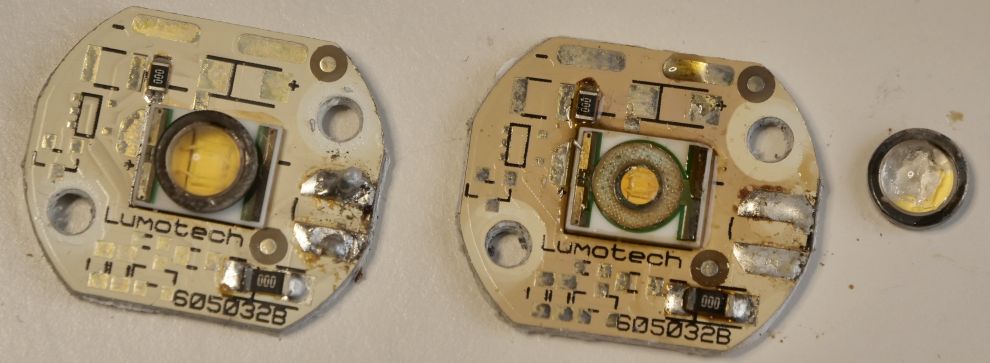
I cleaned everything for a third try and just took a normal soldering iron. With a small blob of ordinary resin-core solder at every pad I then started heating with hot air, to eventually place the LED with a pair of tweezers. Nice effect to see the LED be 'pulled' straight by capillary action of the solder as it got liquid!
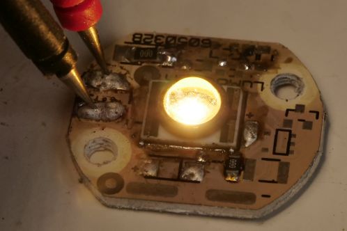 After letting it cool for adequate time (DO NOT BLOW!): Yeah! Yeaheah! It works!
Unbelievable! Considering the thermal abuse this LED-chip had to take (as I most likely heated it for far longer than recommended by the manufacturer) I really find it incredible it still functions.
But, this alone doesn't tell you much. The LED needs to be cooled as well, via the huge thermal pad underneath the LED, that is in thermal connection with the cooling PCB, which in turn is in thermal connection with the aluminium housing everything is built into.
That's why I step up the game slightly...
Thermal check
 The LED has a huge thermal pad on the bottom. As an electrical test alone is not enough to check if the LED is soldered to all its pads, I also check the temperature curve at nominal current, to compare it with one that has been mounted by the manufacturer.
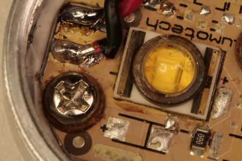
Star-PCB's for high-power LEDs like this one usually feature 1 or more testpoints for checks like this, to be recognised by a gold-plated point on the PCB. On the picture you can see them right beneath the screw and right above the left corner of the LED-chip.
The point closest to the chip takes care of the LED-chip housing-temperature (Tcase). The other point will most likely be used to measure the dissipation of the star-PCB to the housing it's mounted on. As I only took the PCB out and placed it back again and thus hardly anything changed, I'm not measuring it.
Equipment used:
- Multimetrix DMM220 with the temperature-sensor delivered with it set to temperature-measurement
- Fluke 62 mini IR thermometer
- UNI-T 210E current clamp
- Philips PE1540 laboratory power supply in constant-current mode set to 694 mA
The Fluke thermometer was only used to compare the ambient temperature with the multimeter. The difference was so small it could be neglected.
Ambient temperature at testing the reworked LED: 19 degrees Celsius.
Ambient temperature at testing the original LED: 20 degrees Celsius.
It's clearly visible there's hardly any difference. I can safely assume that the LED also makes good contact to the thermal pad and will keep working in a reliable manner. As the ambient temperature was 1 degree higher at the second test, the difference is even smaller.
It does look like the temperature of the reworked LED stabilises a bit earlier. A slightly longer test would probably have revealed some extra information, but as both measurements stayed close to eachother so well, I couldn't be bothered.
Final check and conclusion
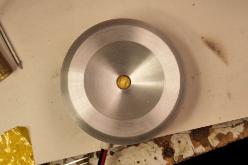
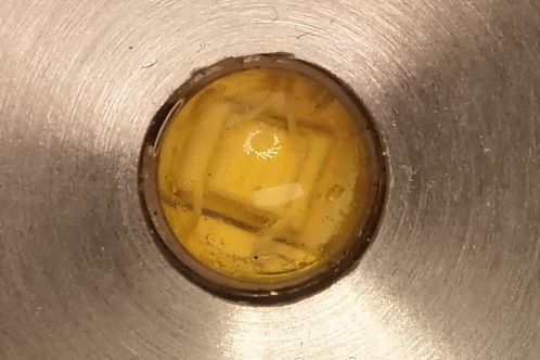 Important: is the LED centered? Though the solder pulled this LED into place so well it could hardly go wrong, the reflector that is screwed on the housing leaves very little room for error. This was an exciting moment, but everything worked out fine.
Concluded: One can do this as a normal human being, although reliability on the long term is harder to check.