Technique - Restoring an Ampeg R-12A tube guitar-amplifier
"Right, hold on... I've still got a guitaramplifier, something's wrong with it, it's really your kind of thing!' is what a good female friend said to me.
"Well, I can always have a look," I said rather nonchalant.
That's how this tube-amplifier was taken into repair or restoration, a task that would prove to be a very learnfull experience.
The original problem
The owner had already told me that she once got a huge shock while playing her guitar and accidentally touching the mesh dome of a microphone with her lips.
As I know capacitors on audio-inputs can go leaky and can cause these kind of defects, I thought that to be the first problem: many musician has already got the shock of a lifetime and sometimes didn't live to tell the tale.
Another option could be a possible ground-loop, but those are usually not that severe. You will notice a prickly feeling, but what she explained sounded far more like a full shock from the mains. As she is an electrician herself, she knows what she is talking about.
A first check
 In my mom's shop, with its own GFCI, testing was little less annoying to the rest of the house. The fuse in the amplifier, still defective from the last time it was switched on, was replaced and the plug was put into a receptacle.
Immediately as I threw the switch, a huge blue flash showed that the fuse had vapourised.
Besides the fuse, the GFCI in the shop also acted, although I didn't completely understand why.
Trying to find the cause: a diagram, anyone?
To be able to look at it in quiet, I decided to keep it at home.
Considering the dead-short I could hardly imagine the fault to be somewhere else then the transformer, so finding out if the mains was actually connected to the transformer in the right way, was my first hunch, especially as it already showed solder-marks.
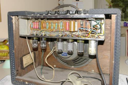
I took a look at the circuit diagram, glued to the inside of the back-plate of the cabinet. Unfortunately, this diagram was not completely correct, what made the search even harder. Even more difficult was the fact that there were no voltages stated.
That the diagram does not match the real situation proved to be quite normal with this amp. There are 'just' 4 different circuit-diagrams out there, which can also show different tubes than the ones mounted inside. 'Mine' had two 6SL7, two 7591 and one 5Y3GT tube.
I looked for help on the Circuitsonline-forum and fortunately, the right diagram was found and linked to.
 Mains supply was at least connected to the right pins on the transformer. I noted down where all the secundary wires connected to and desoldered them.
I then only connected the transformers' primary winding. Again, a loud bang and blue flash indicated a fuse got obliterated immediately.
A test with the multimeter showed a DC-resistance of just 15 Ohm. Possibly, this resistance would drop even further when mains-supply was fed into this winding.
Darn... that was probably the hardest-to-get part!
I first got in touch with the owner, to tell her that this could be an expensive repair.
But her reply was basically: 'I don't care, as long as it works again'. This fortunately also meant I did not have to hunt for 'historic acceptable parts' and could use normal, modern ones.
Transformer-hunt
This - ofcourse - did not meant this was going to be easy. As finding a transformer with both a 5 Volt and 6,3 Volt heater-winding isn't troublesome enough, the amount of current needed on the 5 Volt winding is rather high with 2 Amps.
Via help on the Circuitsonline forum and from information from the tubes' datasheets I kind-of knew which voltages I needed to look for, but necessary currents where a mystery to me. My lack of knowledge concerning tube-stuff was to blame.
For example, I had no idea what kind of voltage to expect after AC-rectification. With silicon-diodes and smoothing caps I knew the voltages would rise about 1,4 times higher, but this proved to be not the case with tubes. Depending on the load, losing tenths of Volts is very normal.
Fortunately, someone on Marktplaats (kind of a Dutch Ebay) offered a substitute transformer, an Amroh P141NN, which was brought to my attention by a member of the Circuitsonline forum.
A capacitor with a line: plus or minus?
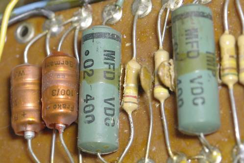 I also had much to learn with the capacitors in this device. The value, marked in 'mfd' was not new for me, but the mysterious line I saw on nearly every capacitor in there, made me doubt whether these were polarised or not.
Good advice from the Circuitsonline-forum again saved me. The line shows which leg is connected to the first layer of foil. Depending on where the capacitor is located, this can lead to unwanted knee-points in the amplifier, because the conductive foil can behave like a capacitor in conjunction with the metal casing.
To prevent that, the capacitor is connected to ground with its first conductive layer, so both are at same potential. Again I learned something new!
I was in doubt again with two smaller electrolytics, with markings '100/3'. Though I knew about the marking 'Value in microfarad/working voltage in Volt', I really was in doubt about the voltage. This however, proved to be right. Back then, such low values were pretty normal. I shopped for substitutes at Jukebok Revival.
Two other caps did have a clear value-marking, but no maximum voltage. Without enough knowledge of the matter I was not fond of 'just going for' 400 or 600 Volt.
Looking through the diagram I found out that one of them was connected between ground and grid 1 of the second 6SL7 and the other wasn't even in the diagram at all. In reality, that one was placed between ground and the second anode.
 Circuitsonline proved to be of help once again. If the power supply was not raised above 400 Volt, I could go for a 400 Volt model. This was the case, as a higher Voltage will damage the rectifier-tube.
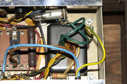
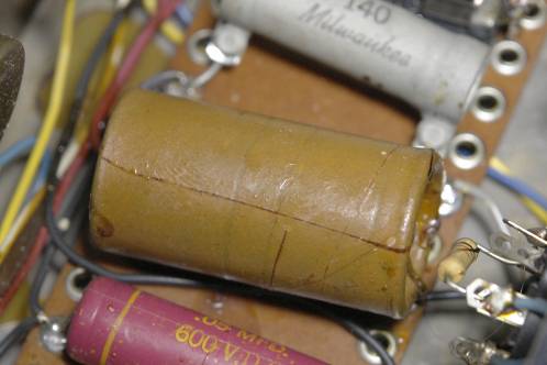
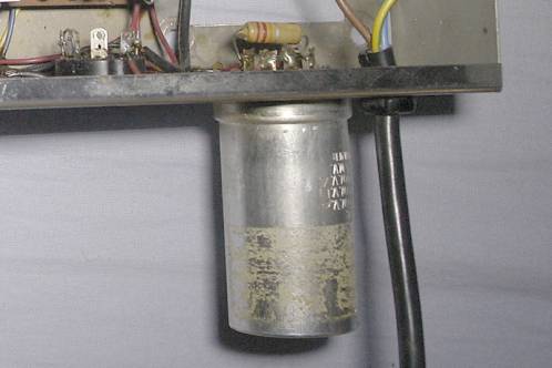
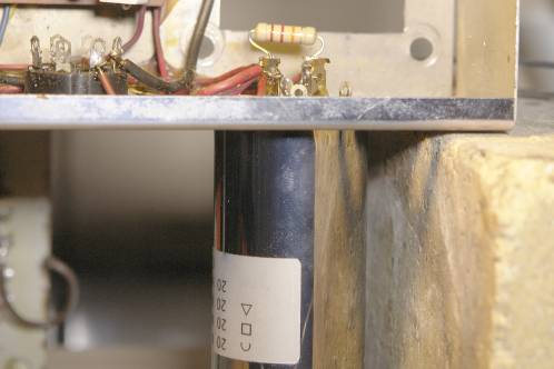
The last piece of doubt was a fat capacitor that was so hard to read in the diagram that I could not make up if this was an electrolytic or a plain capacitor. The thick brown part is shown on the picture.
The part itself also did not show a clear polarity-marking, but it did prove to be an electrolytic.
Finding a substitute proved to be easy as this part is very common as both a capacitor and electrolytic these days.
The remaining components
The remaining parts would mean shopping and asking here and there.
A colleague at work gave me the address to the Dutch company Jukebox Revival, but they did not stock all parts I needed. A few small parts and the multi-cap, with 3 x 20 uF at something like 450 Volts, was only available at Fliptops in the USA. It wasn't expensive, but got expensive because of the shipping costs and customs-fees.
A small mistake by Jukebox Revival forced me to go to my regular electronics-store. Instead of 270 kilo-Ohm resistors, I had gotten 270 Ohm ones. Luckily, Muco in Amsterdam still had some 'historically correct' models in stock. These days, resistors that look like 1/4 Watt types, but have the dissipation-capability of a 2-Watt resistor, are pretty normal. But I sure did not want to put those inside this tube-amp, sitting beside their bigger brothers.
When I tried to replace the potentiometers, one of the knobs unfortunately broke. Removing the knobs was so hard that eventually the inside-body disintegrated. Once removed it also seemed to look like the knob had been put on the shaft with force, as there was a clear spiral-shaped groove.
I think I remember right that there is a difference between American and European pot-shafts, so it could be European knobs had been put on American pots.
Luckily, Muco proved to carry knobs that resembled the original ones and to prevent a difference between the original ones and the substitutes, I replaced all 4.
Starting restoration
 The parts from Jukebox-revival arrived first so I started with most of the capacitors and resistors. Besides being soldered in to great extent, they were also glued to the PCB, which made replacing them very tough.
I took a strange-value resistor into account when I ordered my parts. With 510 kilo-Ohm, it was not an ordinary value and I couldn't get it at both companies. I went for a 470k and 47k resistor in series instead.
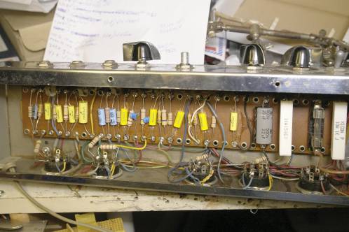
I replaced the components one by one this time. Normally I'd replace many at once, but with this turret board and a diagram that's not completely right I did not want to make a wrong connection somewhere.
During replacement, I also took note of the almost crazy way of connecting things. For someone like me, unknown to tube-equipment, connecting 5 components to 1 pin of the tube-socket is something that almost makes me start considering a better way. It took some perseverance, but I made it eventually.
 This cap was the last remaining part. The multicap with 4 times 20 uF inside, with 3 at a working voltage of 450 Volt and 1 at 25 Volt.
The right connections were my first concern, but onder all the dirt and dust this capacitor also showed a half circle, square and a triangle, just like it's substitute.
But, how was I going to get it out? The thing was soldered into the chassis with its 4 pins. I tried my Weller, but to no avail. On its own it was far too powerless to even start something.
A small torch seemed to be doing something at first, as smoke started coming from the case. That proved to be the small paper-like plate between pins and case of the multi-cap, that was being charred by the torch.
An extra pair of hands
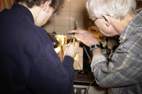 The only solution would be the use of two soldering irons at once. But then I would need an extra hand to remove solder or wiggle the part to be removed.
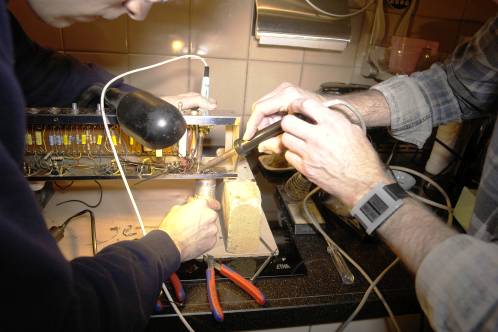
With help from my dad and a hefty soldering iron from his toolbox, some solderstones from my mom (who is a hobby gold- and silversmith), a small piece of wood to protect the stove-top, my 50-Watt Weller, sacrificing tip '8' for that same Weller ánd an extra lamp to lighten up the workplace, we started replacing the multicap.
We needed to heat for long, even though the heat was intense. Slowly we got to the point solder could be removed with solder-wick. As soon as that was possible, the pin would be twisted, as they are not only soldered in place, but also twisted about 45 degrees to also form a solid mechanical connection with the chassis.
 Right after, the pin would be trimmed, so it would hardly bother us.
Despite all the solder-removal and twisting the pins, some of them were resilient and remained in the chassis. When on visual inspection everything seemed clear of solder, it came down to sheer force by just pulling the part.
 We came close to having a few pins left behind in the chassis while the case itself would have been retrieved.
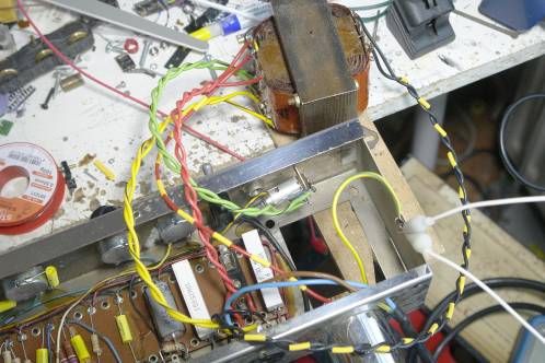
The pictures of combined forces are taken by my mom, who liked this soldering-battle.
After removal the holes in the chassis were thoroughly cleaned and the new cap was placed. Ofcourse, I also twisted the pins on that one to form a rigid connection. I could then easily solder all the pins with a nice blob of solder.
You can see the shiny part on the picture. You also see the marks denoting the different capacitors inside and are also shown at the connecting pins.
After soldering the cap to the chassis, all the wires were resoldered into place.
Wiring the new transformer...
 It may look like I was done, but the transformer remained.
I thought about using the original wiring from the old transformer, but it proved to be too short and was firmly glued together as well.
I went for new 'VD-wiring'. With pieces of yellow heatshrink I marked the red and black wires, as I did not have striped red-yellow and striped black-yellow wire in stock.
The green-black striped wire was easier. I placed the wires in a vise and pulled it straight, and pulled a black line on the insulation. I then twisted the wires, which also happened to all other wires that had been twisted before I started restoring this thing.
First light after restoration
Applying power for the first time (with the owner next to me, so twice as thrilling) was done with a variac in series.
This way I could slowly raise the voltage and see if anything went wrong.
I used the variac inside my resistance-soldering unit, which I supplied with a connection to connect other equipment than the built-in transformer (what a foresighted mind I have...).
The foot-switch also proved to come in handy, as cutting power on a malfunction was very easy.
Testing was once again done in my mom's shop, to avoid angry people inside the house should a short arise.
On the variac-output a multimeter was connected and also the rectified voltage inside the amp was being monitored by a multimeter.
I turned the variac's knob till the light on the amplifier started glowing. From that point on I started increasing the voltage and kept listening for strange noises and keeping a close eye for possible smoke.
Around 110 Volt I waited for a while, checked for abnormal temperatures here and there and went ahead with power-increase when nothing strange was found.
Surprised and in dead silence both me, the owner and her husband, I kept pressing the footswitch when suddenly, after a few minutes of warming-up, noise suddenly increased and then a stable, very soft hum could be heard from the loudspeaker.
There was no guitar to test it further, but the fact everything had remained intact was already quite something.
The rectified high voltage was on the high side though with 325 Volt. I suspected my meter of being incapable to handle a not so smooth DC-voltage, but as the owner got out her Fluke from the car and it displayed the same result, it had to be right. Something to have another look at, as the voltage is right on the maximum guideline for the rest of the tubes.
Besides, the transformer still had to be mounted and shielded. The owner knows a steelworker able to make it from the right material, so that's something for the future.
She took the amplifier home with her and I now await a thorough test with a guitar, but I suspect that will take at least a few years...
Parts used
The bill of materials to restore this amplifier is rather big. Although resistors usually don't suffer from aging much, I did decide to replace them as well, as the cost is low.
The parts listed below are parts I found in the amp I got my hands on and tolerances have been copied for clarity. There are small differences in these amps, so check yours thoroughly. The 510 kilo-Ohm resistor was replaced with a 470 kilo-Ohm and 47 kilo-Ohm resistor in series, so both show 1 extra added to the total needed.
The list also shows an indication of the costs involved: if you have to buy a new transformer, this will surely increase the costs. If later, with a real test, it shows the output transformer is defective as well (which would surprise me considering the stable hum from the speaker), the costs could be on the rise.
| Resistors (2 Watt, unless stated otherwise) | |||
| Amount | Price | Total | |
| 220 Ohm | 1 | 0,15 | 0,15 |
| 140 Ohm 10 Watt | 1 | 0,60 | 0,60 |
| 1000 Ohm 10 Watt | 1 | 0,60 | 0,60 |
| 1 kilo-Ohm | 4 | 0,15 | 0,60 |
| 2,2 kilo-Ohm | 1 | 0,15 | 0,15 |
| 10 kilo-Ohm | 1 | 0,15 | 0,15 |
| 22 kilo-Ohm | 1 | 0,15 | 0,15 |
| 47 kilo-Ohm | 6 | 0,15 | 0,60 |
| 120 kilo-Ohm | 3 | 0,15 | 0,45 |
| 270 kilo-Ohm | 3 | 0,15 | 0,45 |
| 470 kilo-Ohm | 4 | 0,15 | 0,60 |
| 5,6 Mega-Ohm | 1 | 0,15 | 0,15 |
| Potentiometers | |||
| Amount | Price | Total | |
| 1 Mega-Ohm | 2 | 2,00 | 4,00 |
| 470/500 kilo-Ohm | 2 | 2,00 | 4,00 |
| Capacitors | |||
| Amount | Price | Total | |
| 500 pF 400VDC 20% | 2 | 0,20 | 0,40 |
| 0,002 uF/2 nF 600VDC | 1 | 0,50 | 0,50 |
| 0,01 uF/10 nF 200VDC | 1 | 0,40 | 0,40 |
| 0,02 uF/20 nF 400VDC 20% | 5 | 0,8 | 4,00 |
| 0,05 uF/50 nF 400VDC 10% | 3 | 1,00 | 3,00 |
| 0,05 uF/50 nF 600VDC 10% | 1 | 1,00 | 1,00 |
| 0,1 uF/100 nF 400VDC 20% | 1 | 0,25 | 0,25 |
| Electrolytics | |||
| Amount | Price | Total | |
| 20 uF 450 VDC | 1 | 4,00 | 4,00 |
| 25 uF 100 Volt | 1 | 1,00 | 1,00 |
| 100 uF 16 of 25 Volt | 2 | 0,25 | 0,50 |
| Multi-cap 20x20x20 uF 450VDC + 20 uF 25VDC | 1 | 30,00 | 30,00 |
| Transformer | |||
| Amroh P141NN | 1 | 52,00 | 52,00 |
| Remaining parts | |||
| Arrow-knob | 4 | 2,80 | 11,20 |
| Total | 120,75 | ||