Technique - Fixing a Philips Master Ultra Output LEDtube
A rhythmical glowing LEDtube...
Somehwere in 2021 at work, I was asked to take a look at the lighting in the machine-shop. Something was flickering there. I got curious immediately, as the machine-shop, just like almost the whole company, is fit with LEDtubes only since 2017 or so.
In the shop itself the failure was clear: one LEDtube was glowing on and off in a rhythmical fashion and that was probably even more annoying than the hard on/off flickering a fluorescent that goes bad usually presents.
My chief had immediately put it in the recycling-bin when he walked in, but I at least wanted to try if I could find out the cause to this. Considering the glowing, the splashwater- and impactproof fixture with zero air-ventilation the thing was mounted in (and thus sustaining a far higher ambient temperature than these are rated for) I could only think of a problem with an electrolytic capacitor.
For completeness: this article is about a Philips Master Ultra Output LEDtube with modellnumber 9290012983, that outputs 3700 lumen in color 865, is 1500 mm long and draws 24 Watts of power.
Let's open it up! (And that proved surprisingly easier than I expected...)
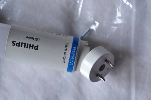 Take the LEDtube in your hand and find the end marked with 'EM/MAINS' on it. Remove the Phillips-screw that holds the rotatable socket in place. Caution, there's also a spring in there!
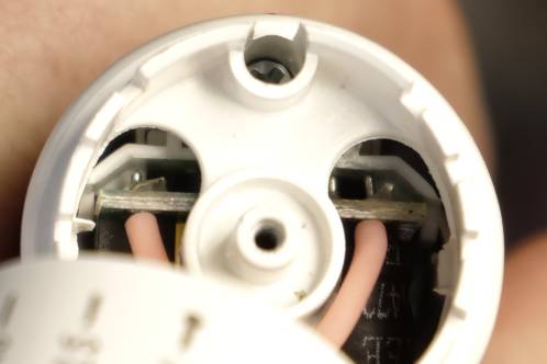
 With removing this screw you can already get a glimpse on the inner workings of this thing. The only thing you need to do now to fully dis-assemble this thing is to unsolder the pink wires going to the socket that meets thefixture.
The plastic these pins reside in is surprisingly heat-resistant and can take quite some abuse during soldering, as I found out.
 With a Phillips screwdriver (yes, really, that's how easy these can be dis-assembled) you need to remove the screw that mounts the plastic sleeve to the heatsink of the LEDstrip. This screw lies well-recessed in the plastic sleeve.
Remove the plastic sleeve after removal of the screw.
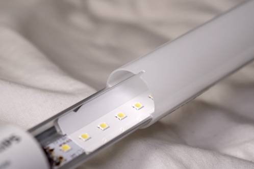 Get to the other end of the tube and you can now slide the heatsink with the LEDstrip and power supply attached to it out of the semi-transparant tube.
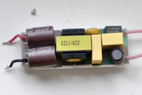
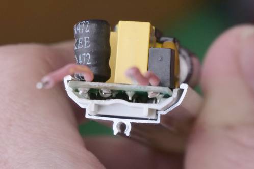 And this is what it's about. The powersupply. The power-supply resides in a nice plastic (for insulation) cradle, which in turn effortlessly slides into slots on the aluminium-heatsink. Some thought went into this!
 The only two solderjoints you have to desolder to be able to inspect the powersupply are the ones coming from that supply, going to the LEDstrip plus and minus. Because of the heat-sink, even my 80-Watt Weller had a bit of difficulty getting the job done.
Once desoldered, the PCB itself beautifully slides out of the plastic cradle. They really put some good thought into this!
I expected the electrolytic caps to be the problem and desoldered the two 160 Volt 100 uF Aishi caps (well, that brand is familiar...)
These had degraded quite a bit already (beyond 10 percent) but the ESR was below 1 Ohms. And that's a good value at these voltage-ratings.
Both caps were soldered back onto the PCB.
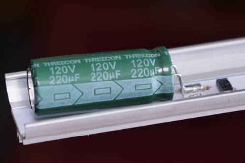 I then focussed my attention on the big green Threecon cap at the other end of the tube, a quite fat 220 uF at 120 Volt rating. This proved more reliable when it came to capacity-degradation when measured, but this one also had a good ESR, so I was in the dark here.
You also see a diode-like part on the photo, I expect some suppressor against voltage spikes.
I mounted everything back together again and hoped that just a few resoldering-jobs here and there would solve the issue. I connected power and... now the thing was completely dead.
I desoldered the PCB from the LEDstrip again and took another good look at it. I couldn't find anything out of the ordinary, but did find out already that the PCB was very vulnerable. When desoldering the capacitors some PCB-traces had already sustained damage and only a blob of solder could connect everything together again.
When I just started going over the biggest components, the parts that unleash the most mechanical stress on their solderjoints, I hit the right one at a small coil near the AC-in. By coincidence, I soldered the left pin first, which made the whole part wiggle loose in the PCB. Right! How!? Let's get the magnifying glass!
The perpetrator: a damaged PCB-trace
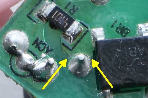 The magnifying glass revealed a PCB-trace that had been cut. And that trace was carrying all the incoming current to the bridge-rectifier.
Also pay attention to the 470 kilo-Ohms SMD-resistor above it, that looks like it took a beating from the flashing, or isn't really up to his task anyway...
Status: Fixed!
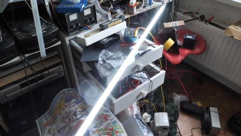 With nice blobs of solder, I connected the powersupply again and turned it on.
Yes-yes! It's back to life!
It's a pity that the reliability has gone down the drain. The PCB is so susceptible to mechanical stress that even during re-assembling the tube, another cut in a PCB-trace occured, which involved another blob of solder to get the tube going again.
Concluded
This 'device' has been well designed, I really can't say any different. No weird screws, no glue or hard notches that click. Everything seems to be designed to be able to take on repairs. It could be that regulations demand a design that makes taking it apart easy to make recycling better.
It's a pity however that the PCB is so vulnerable after 4 years of use in a (okay, okay...) fixture they are not supposed to be put in.