Technique - Fixing a Metabo ASC 30 batterycharger
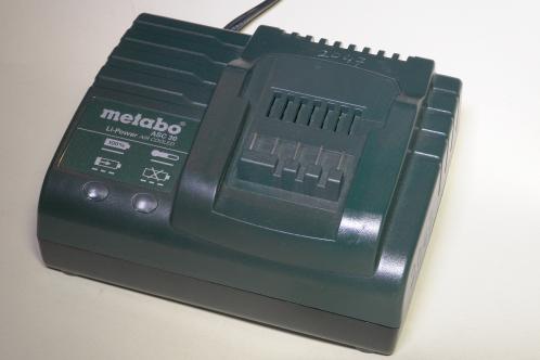 Electrical tools in the Netherlands used on a professional basis, need to be tested once a year for electrical safety, by means of the so-called NEN-test.
At the annual NEN-test in 2017 at work, this batterycharger from Metabo was rejected due to the simple fact of being completely dead. That was rather surprising, as the series of cordless drill's we have that got this charger with it, were not around in the company that long yet.
I saw the charger at the bottom of a bin, while I was in doubt for a while. I then decided that my urge to research the thing won from some reluctance. To learn something, I decided to take it home, with the promise to bring it back if I was able to fix it.
I did test it before I took it home, but it proved to be dead indeed.
 Opening this thing up was something I already did at work, to rule out a simpel defect like a loose connection or blown fuse, and not taking it home for something I could fix at scene.
To open this device, you have to remove 4 rubber feet on the bottom by pulling them from the bottom. These 4 feet cover the holes where the screws are.
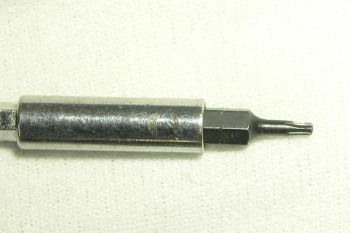
These screws have a Torx-head. The most annoying part is that the screws are in rather deep: with a standard bit-holder and Torx-bit you're just unable to reach them.
There is a simple solution by placing 1 or 2 stainless-steel M3 nuts in the bit-holder and then placing the Torx-bit. This way, there is enough length to reach down to the screws.
I did have Torx-wrenches at work that were long enough, but with the long side in (they're just like hex-keys, with one short and one long side) it was hard to loosen the screws, so I chose the bitholder.
Metabo ASC 30 batterycharger opened up: first impression
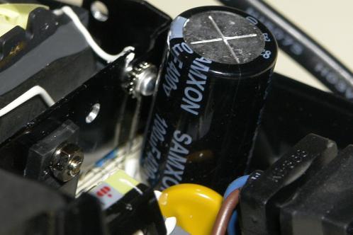 On first glance inside this thing I immediately saw something that didn't make me happy. The primary cap was clearly stating it was 'made' by Samxon. If there is one brand that has suspicion written all over it...
This cap is not the only one by far: there's not a single cap inside that's from a reputable brand. The other ones are Samxon's as well, HC's or something else.
I stumbled across a Licon or something for instance. The marking on it's housing was so bad that I could hardly figure out what the 'brand' was.
Repairing: Attention and a word upfront
Like every switchmode power supply, this one features a fat cap on the primary side as well, which holds a nice 325 Volt on it's connections after pulling the plug. In my charger, this one takes a while to get it's voltage down to a safe level (3 full minutes to get the voltage below 40 Volt). Pay attention to that when opening this device!
Besides that, many components on the PCB, including an opto-isolator, are mounted underneath the big transformer. This makes replacing these components nearly impossible.
The component-marking on the PCB is bad, especially the ones that consider the caps. The positive and negative marking was so bad at some that only pictures could tell me what their orientation was. Pay attention when you are desoldering these!
Like all of the above isn't enough, the whole PCB is covered in an annoying, thick layer of plastic on both sides. That's probably great to get everything more solid in a mechanical way and to reduce the chances of damage by moisture, but the layer is so thick that I could only penetrate by using sharp pointed testpins from Hirschmann. Caution! This can easily give you a false-safe reading on the state-of-charge of the primary cap!
The plastic also makes sure that soldering becomes a smelly job. Desoldering and removing parts is so hard that some reasonable force is needed. Perhaps you get my point: many measures have been taken to make sure fixing this is as unattractive as possible.
A first diagnosis by use of an AM-radio
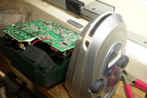 I wanted to diagnose this thing first by using an AM-radio, to listen for switching-noises. I could not find a blown fuse, but maybe something else important was blown which caused the malfunction.
The radio however, emitted a clear 'tock, tock, tock' sound, most likely produced by attempts of the power supply to start, but failing to do so every time.
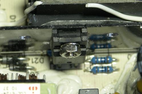 This made me look at the primary-side FET first.
Even the way this part is mounted is ridiculous: everything, really everything has been done in this thing to make sure repairs are a shit-job. You can't get to the screw that holds the FET to the heatsink, as the head of the screw is facing the transformer.
With a socket spanner and some fierce turns, I managed to loosen the nut. The screw could just be removed by taking it out of the heatsink, past the transformer. I would at least turn the screw around.
Checking the FET with a Peak Atlas DCA75 proved that it was in good working order.
A second check with LCR45 and ESR60
I had checked the primary cap and a few others on first instance. I unfortunately damaged the PCB at one point, which made me improvise with extra solder and removing some of the solder-resist.
The desoldered caps were checked with the Peak Atlas ESR60: this did not provide any bad results. The ESR was rather high with about 1 Ohm, but the rest of the specifications were good and checking the cap a little further with the LCR45 showed that specifications at 1 kHz were still very decent.
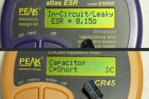 That's why I decided to take another look at the caps, but now the remaining ones, as Samxon just isn't a reputable 'brand'.
After having checked multiple capacitors, with results that only got close to 'Possible cause, but unlikely' I was down to three remaining.
Along those three was a big one, a 25 Volt 330 uF type without a clear branding on it's sleeve. When checking this one, C110, I found 'the wrong one': The ESR60 almost immediately measured an ESR, but took it's time to check the capacity. After about 5 seconds, it was labeled as 'Leaky/In-circuit'.
A further check on the LCR45 was as clear as possible: Shorted.
I replaced this one with a Panasonic FC capacitor with a capacity of 470 uF and equivalent voltage. In general, the capacity is not a superstrict fact and I did not have a 330 uF capacitor at hand.
 I wasn't there yet. C106, a small 10 uF 100 V cap and again a Samxon, proved to be in bad shape as well. The ESR is rather high with about 1,6 Ohms and capacity has already dropped beyond 10 %.
Though most capacitors have a tolerance in capacity that is plus or minus 20% and this thus falls within tolerance, I think it's a very bad result for such a young device.
It's no excuse that this cap is right next to a heatsink: only during charging, the temperature will go up quite a bit, the rest of the time the device is in stand-by mode and is at ambient temperature.
I did not replace this one (because I don't have these types at hand) and first checked if replacing only the 330 uF cap would solve the issue.
Status: Fixed
 After checking the PCB, I found a free socket and plugged it in. The red LED lit shortly, after that the green LED and the fan was shortly activated. That's a good sign!
I closed the device again and placed the screws back and slid on one of my own batteries. The charger went into charging-mode immediately and after about 30 minutes, the job was done.
Unbelievable! One capacitor costing only 27 Eurocent is causing a complete batterycharger to go dead! Just because the capacitors are so cheap! Metabo, shame on you!
I also don't get it, as this charger is capable of charging a great number of different batteries with all kinds of voltages. I think that cutting corners like this will only backfire on you as a manufacturer.
If these chargers would have been useless by now because there is a new battery-system for years already, there was something to say for a lifecycle of about 5 years, but the batteries for these chargers are still being used throughout the whole range of products from Metabo.
Special point: PCB-shunt
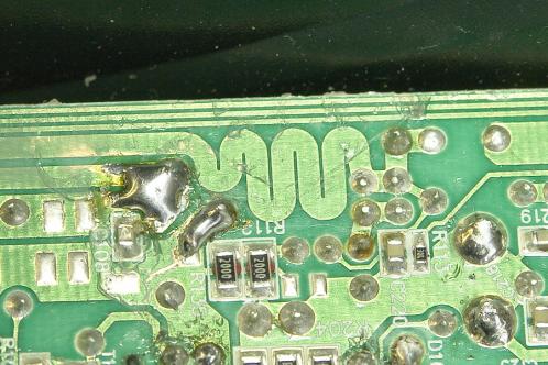 You can find some special points on the PCB of this charger. One of them is this bendy PCB-trace.
I first thought about a simple (but effective) way of high-frequency noise-supression, but I think it's more likely to be a resistor to measure voltage, called a shunt, in the form of a PCB-trace. This because there is a smoothing-cap at the beginning of the bendy trace and after the few bends, a fuse connects this trace to the positive terminal of the battery.
Between the fuse and the 'end' of the bendy trace are two precision-resistors on the other side of the PCB. I can only think of measuring a small voltage-drop over this PCB-trace by means of these 2 resistors, which provide feedback about the condition of the connected battery.
Take care not to damage this PCB-trace! The thickness of the copper layer is most likely causing the right drop in voltage across the trace and changing the thickness by an accidental mishap with a screwdriver or repair with a layer of tin or a wire, could mess with things.
Special measure in this charger: Spark-gap against extreme surge-voltage
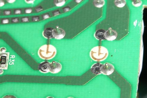 On the bottom of the PCB, I noticed something at the first inspection. I saw something that looked like a spark-gap!
A short search on the internet proved that this is indeed a sparkgap.
Allthough this charger also has a varistor on board (a resistor that is hardly conducting at mains voltage, but gets more conductive as voltage rises) and therefor has a simple but effective surge-voltage protection, there are also two spark-gaps.
At mains voltage, there is nothing happening: at around 2 kiloVolt, the creepage-distance between the points that are sharp and un-isolated on purpose, will be insufficient for the air to keep acting as an insulator and will cause a conductive path, which will create a spark.
This spark will most likely cause the fuse to blow, as it's nothing more than a short.
This is a safety-feature to keep the varistor in 1 piece, as that part can only take a certain amount of energy.
A short 400-Volt spike is probably no big deal, but a big surge because of an indirect lightningstrike will cause the varistor to explode. Now, the sparkgap will take the blow. Unfortunately, that could be the end of the charger when that happens. The spark-gap can not be replaced and the spark could have made a permanent conductive path between the contacts.
Australian David L. Jones, better known as Dave from EEVblog, found the same sparkgap in a different power supply and has a short talk about that and other sparkgaps.
01-08-2020: A lot of e-mail and a second charger (+rectification 08-01-2022!)
When I uploaded this article in January 2018, I could never have expected that it would lead to such a response.
I got messages from people all over Europe who were facing the same problem on a monthly basis and sometimes even more often than monthly.
Besides the problem (and solution) all these people had another thing in common: only few people had acquired this charger a long time ago and thus felt just as fooled as I was, although mine was not a private buy.
The easy fix was reason enough for me to buy another charger of this type over the internet. As for 15 Euro and 1 capacitor costing only 27 cents, I would have no trouble selling the unit on with a profit.
So, as I got in the second unit I immediately got out the screwdriver... to find out this one was built completely different!
08-01-2022: But that's correct, as this was an ASC30-36... I could check this because I saved the enclosure.
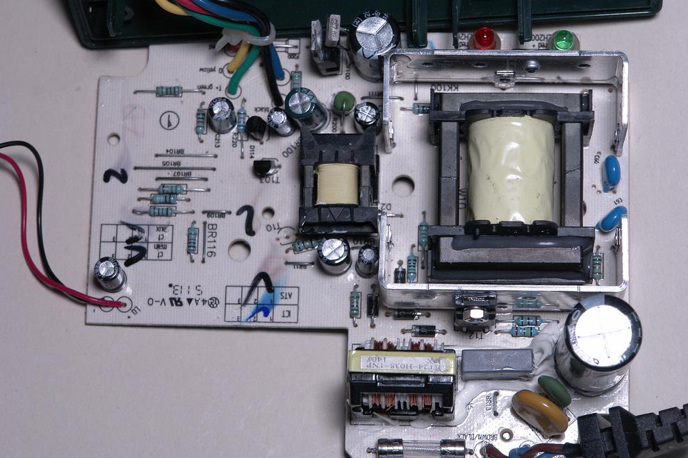
Another difference: This was one really was dead. Listening with an AM-radio resulted in nothing but static: no sign of life whatsoever could be heard.
All caps measured okay, or at least not with values of any concern.
Besides a lot of other components and a FET that can't be desoldered from the board as the screw that mounts it to the heatsink can't be removed AT ALL in this one, this unit also featured a linear voltage regulator. As that one proved to be prone to (over)heating, there also was a thermistor or thermal fuse attached to it. The glue used made it hard to determine what it was exactly.
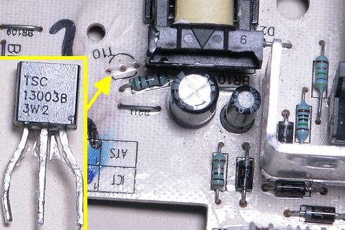 I don't remember how I found out about this part, but transistor T10, a TSC13003B, was dead. The component-detecter kept saying I didn't connect anything.
A test with a (by paper-comparison) equal type, as the TSC13003B is hardly available anywhere, didn't yield any result.
Another surprising candidate was the resistor right next to the diode. I can't remember the marking on the PCB and thus don't know if I remember it right. This resistor proved to be defective as well by going open-circuit.
Quite surprising given the marking that denotes a 1 or 10 Ohm value (the rings were hard to read through the layer of plastic). Surprising overall as resistors are at the bottom of a top-3 of usual-suspects, with a high level of rarity.
Via a French forum I found out the problem was most likely to be found around or in one of the unknown SMD-ICs on the other side of the PCB. That was the moment I quit and brought this charger to the disposal facility.
08-01-2022: There's just no end to this...
 In the beginning of this article, the response was huge and I got loads of e-mail from people who were facing the same problem. Eventually, the numbers of e-mails dropped.
But it's not completely down to zero yet. On a regular basis I still receive messages from people who managed to revive their charger with the help of this article and I have received multiple requests if the charger could be shipped to me for repairs.
I usually don't do that, but sometimes, I make an exception.
This one too was having the ticking-disease. Again, this charger looked brandnew as well, but did have the bad-cap problem. This ever more starts to look like a bad batch of parts that take out these chargers in numbers.
With a Panasonic FC electrolytic of 470 uF and 25 Volt, this charger was revived as well and could be shipped back to the owner. To reach even more people, I also made a quick video about it this time.
For everyone who isn't capable of doing this yourself: My best advice is to look for a repair-cafe. The Dutch electronics-forum of Circuitsonline.net provides a section where users can place an ad, looking for a repairman (or woman!). They usually are friendly for foreigners as well. One has to register to be able to place an ad though. Looking for an electronics forum in your own country is probably the better option ofcourse. I've got a regular job besides my website and I already feel I'm always short on time and thus was not thinking about making a living out of this...