Technique - Dummy-battery for Bose QuietComfort 25 headphones
Word upfront
Of course, you handle solely at your own risk. Don't come knocking on my door if you fry your headphones.
So... you are getting on a plane?
When I was about to step on board of an airplane at the end of 2018 for the first time in my life, I got all kinds of advice about what I shouldn't do and especially what I should do. On number one: Buy 'noise cancelling' headphones against the airplane noise.
That really proved to be a good advice and I did not expect those to work so well.
Before my buy, I did an extensive internet-search about the pro's and con's of all the different models out there.
Models working with Bluetooth were a no-go for me, as it becomes a completely useless thing once the battery is drained.
One of the few wired models would still provide sound when the battery couldn't support noise-cancelling anymore, be it with lower quality.
And thus, I bought the nice Bose QuietComfort 25. Lightweight because of the small AAA battery that makes it run for about 30 hours.
More and more, especially in summer, I started to use it at home as well, when the noise from the outside world would become to annoying for editing video or just listening to music.
It does a good job on suppressing those unwanted sounds as well, but yeah... that battery... With a couple of hours of use per day, it drained far quicker, you easily forget to turn it off and if I fell asleep with noise-cancelling active, a few hours would pass in no-time.
Ergo: in short time I started eating batteries. Couldn't I think of something for that?
Power supply with a dummy-battery
 The warranty passed eventually, so I started to think of a dummy-battery, a common way to power something via a bigger, external battery or even mains power.
The small hatch for the AAA-battery did make this a bit tricky though.
I measured the size of an AAA-battery with a calliper (with an insulating plate between one of the jaws to prevent a short!) and found a piece of acrylic round-rod with 8 mm diameter.
That's smaller than the 10 millimeter diameter of the battery, but covered in a layer of heatshrink, I would probably get close to the same size. Two M2-screws from the junkbox and very thin copper-clad PCB was also at hand.
With an old USB-cable to sacrifice I was almost ready to go.
Bringing the voltage down to 1,5 Volt
I got stuck on the power supply, which I wanted to get from a USB-port and thus had to be lowered by a factor 3,3.
The headphone is not made for power via a dummy and without any information on the electronics inside, I did not want to go for just a couple of diodes in series to lower the voltage. This because the USB-connection introduces a ground.
The jack-cable features a signal-ground that connects to ground at the PC, with all possible consequences one can think of. It it wasn't for a ground-loop that would only introduce some annoying hum, than it would be something worse that would really damage the headphone for good.
 I therefor started a search for small DC/DC converters to bring the voltage down to 1,5 Volt. Unfortunately, I only found those in non-isolated form.
Isolated, I could only get ones that brought the voltage down to 3,3 Volt.
For some other electronics-messing-about I still had a 5 to 3,3 Volt converter laying around, able to provide well ample current (500 mA) for this situation. With a few diodes in series, this worked well.
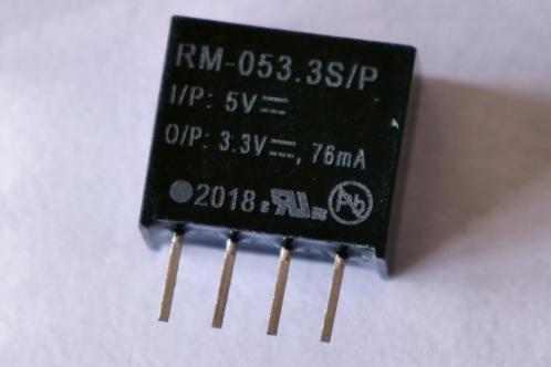
As nominal current would not exceed give-or-take 35 mA, I bought a far smaller variant made by Recom, the RM053.3S/P. With 76 mA available current, there's some margin on the current being drawn. Together with a couple of diodes, I would be able to get the voltage down to a sufficient level.
Looking back now, I could have put a non-isolated converter behind an isolated on to get the desired voltage.
The 'circuit-diagram'
...probably shows some components that seem a bit odd. Resistor R (82 Ohms) is there to get some current flowing through the diodes. Besides the voltage from the converter being slightly higher without a load, diodes without any current flowing through them hardly have a noticeable voltage-drop. With noise-cancelling off, the voltage rises to slightly over 3 Volts.
The resistor makes sure the voltage stays at about 1,85 Volts, dropping to about 1,6 Volts with noise-cancelling on. That's still a bit tight in my opinion, but the fresh AAA-battery hardly did a worse job at 1,55 Volts.
Electrolytic capacitor C is a 100 uF type. During testing, I found that loud noise caused the voltage to drop so much the noise-cancelling would stop working for a short time. The electrolytic provides an adequate buffer during those peak demands.
Diodes D1 and D2 are standard 1N400x diodes. A test with 1N4148 diodes proved that the voltage across them during peak-currents increased so much that it would constantly cause the noise-cancelling to turn off.
I found a nice 'enclosure' at the electronics-shop - I don't think they make them any smaller - which provided more than enough space to fit everything in (that's quite a thing, it is usually the other way round).
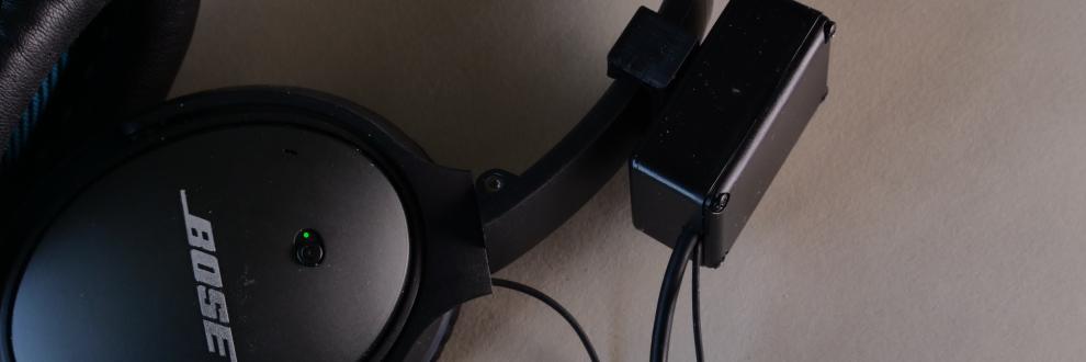
The dummy-battery and mounting the enclosure for the converter
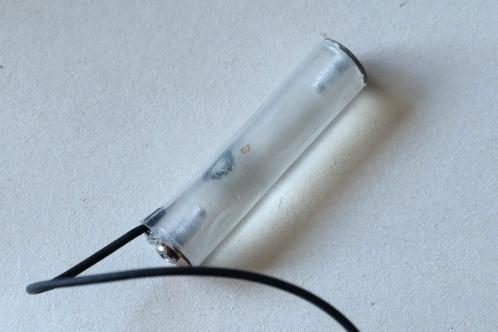 As the battery-compartment on the headphone itself is so small, not only the dummy-battery itself needs to be carefully designed, it also needs a clever way of getting the wires to the outside world.
Luckily, the battery-door provides a nice slot. I found an old pair of in-ears for a mobile phone, with the nice flexible silicon-insulated wire. The wire to one of the in-ear speakers would serve as the power-supply.
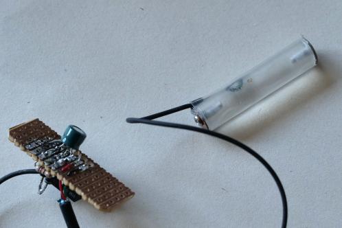
M2-thread was cut on both ends of the acrylic rod.
After soldering the 2 wires to small pieces of the copper-clad PCB, I mounted those at the ends of the acrylic rod, which was then covered in heatshrink. Take care when shrinking that you don't deform the acrylic!
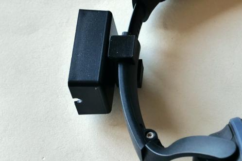 With the 3D-printer my sister bought in 2020, I could get a nice holder made by her. Till then, everything was tie-wrapped to the headphone as it was still a test, which was a bit difficult when I wanted to remove the dummy-battery.
A kind of C-clamp fits snugly around the right-ear 'arm' of the headphone, by first extending it all the way and then sliding it over. It is the mounting point for the small cabinet, that I mounted with 2 small plate-screws.
You can download the file here:
Settings for the slicer:
- Speed at first layer: 15mm/sec
- Layerthickness: 0.16mm
- Perimeters: 60mm/sec
- Infill: 40% Gyroid
- Vertical shells (perimeters): 10
- Solid layers bottom and top: 3
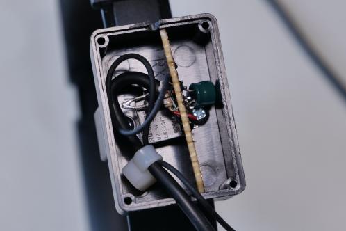 A tie-wrap acts as a strain relief for both cables. A small opening in the enclosure makes sure the cables can exit to the outside world. Straight after, I gently pushed everything inside the enclosure and mounted the lid.
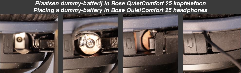
As said, the battery-door is a bit of a catch to figure out. You'll need to place the dummy carefully.
Firstly, you will have to put in the dummy-battery with the wire on the side of the ear, till it completely fills the compartment. Then route the wire through the small slot and push the door like you would do with a battery.
The only downside to this approach: an extra cable, that always gets tangled with the audio-cable.
Done!
Now you only need to plug in the USB-cable somewhere. Powerbanks unfortunately are not a solution as the current drawn is well under 100 mA and will make them turn off automatically. A computer or phonecharger will definitely work.
And then... you can listen in peace and quiet WITHOUT eating batteries like there's no tomorrow!